-
But in practice a perfect core is rare and we find the measured core rise and the volume of material recovered from each drive to be greater or less than their theoretical amounts. When drilling gold placers, any deviation from the norm is important because when basing value calculations on small-diameter holes, any deviation between the theoretical sample size and the actual sample size becomes critical. For this reason, any excess or deficiency of core should be taken into consideration during the calculation procedure and suitable corrections applied.
Erratic drill cores are caused by a variety of things. A rock partially blocking the drive shoe may move downward with the pipe and force material beneath it to one side. The result would be a deficient core. A normal-length drive in tight ground often gives less core than it should. This is caused by material packing in the pipe and as it becomes more difficult for the core to enLer, some will be pushed aside. The experienced driller sometimes prevents this by drilling a short distance ahead of the shoe. He should not, however, "drill ahead" without permission of the engineer in charge because there are cases where drilling below the shoe creates more problems than it solves.
When a drive is made through tailings or through loose, rocky ground, the initial core rise may be normal but subsequent pounding by the drill bit tends to push the core material back down the pipe and out of the hole. As a result. the pump may get little or no core recovery. In loose, wet ground there is always danger of overpumping, that is, pulling excess material in from under the drive shoe. In "running" ground the driller should keep the drive pipe full of water to offset outside ground water pressure (which tends to push loose material into the pipe) but in spite of such precaution. excess cores can be expected.
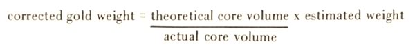
Ideally, a 1-foot drive should produce a 1.7-foot core rise; this 0.7-foot increase reflecting the difference in diameters between a 6-inch drive pipe and its 7 1/2-inch shoe. But in practice we rarely get the theoretical amount of core. Instead, we get too much or too little for a given drive. Now, the most important thing to remember is that if a placer drill sample is to he meaningful it must take into account the amount of material actually obtained from the sample point in question. Stated simply, if a drillhole increment contains too much core its value will have to he downgraded. If it contains too little core its indicated value may he upgraded. Most placer engineers base their adjusting procedures on either the ratio between theoretical and actual core rise, or theoretical and measured core volume. Depending on which is used, the basic rormula would be:
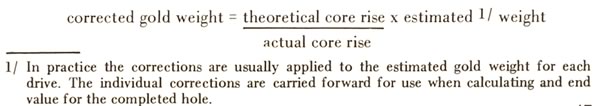
In general practice both core rise and volume corrections will be considered, but the most conservative correction will be used. Experience has shown that adding large plus corrections at their full value is likely to result in an overestimate and for this reason some engineers limit any "corrected" figure to an amount not more than double the initial uncorrected figure. They will, however, apply the full amounts of all minus corrections, this being considered a form of safety factor. Actually, in the case of gold placers, there are no universal rules for interpreting or "correcting" the samples obtained from churn drilling. Validity of the end result will depend largely on insight and the experience of the engineer in charge.
Many of the details to be considered when logging placer drill holes and processing the data have been given by Harding (1952, pp. 96-98) and Daily (1962, pp. 80-88), to whom the reader is referred. From these it will be seen that placer drilling requires specially trained personnel and that "correcting" the drill results is a specialty that is not within the experience range of most mining engineers. For this reason, any placer valuation based on drilling should be viewed critically until the qualifications of the engineer in charge have been established. This is particularly true where the original drill logs are not available for inspection, or where drilling cannot be compared against past production from the particular deposit or area.
Something should be said about the so-called "Radford" factor 1 / which, when used, applies an arbitrary plus correction to the drill hole calculation. Early placer drillers soon became aware that their actual core recoveries were something different than the theoretical amounts and it was reasoned that because of progressive rounding of the cutting edge, a 7 1/2-inch drive shoe will in normal use cut something less than 0.3068 sq. ft. of material. Mr. Radford, on the basis of his experience and observations, concluded that the sample taken in by a 7 1/2-inch shoe driven 1 foot will, on an average, be 0.27 cu. ft., or as more commonly stated, 1/100 of a cubic yard per foot of drive. This figure was widely accepted by the early drillers.
The Radford factor is applied by substituting 0.27 for "A" in the basic equation where cents per cu. yd. =
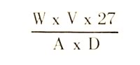
Using our earlier example this equation would become:
The first calclation using the theoretical drive shoe area of 0.3068 sq. ft. for "A" gave a value of 13.7 cents. Substituting 0.27 gave a value of 15.6 cents. It is seen that use of the Radford factor increased the calculated value by 12 percent.
In some cases other factors were applied to decrease rather than to increase the calculated value. Usually, the Radford or other factor was applied to the entire hole, that is, they were not applied on a drive-by-drive basis. It should be obvious that the use of any arbitrary correction factor is hazardous because ground character will vary in different properties and for that matter in different parts of a single drill hole.
Today, considerable difference of opinion exists concerning the validity or use of the Radford factor. It has been mentioned here to alert readers who may not be familiar with placer drilling that many of the placer valuations found in reports, particularly in old reports, have been based on calculations employing the Radford or other arbitrary upgrading factors.
In arctic regions, permanently frozen ground is drilled without casing with exception of a short length at the surface to serve as a collar and tool guide. Sample volumes are determined by measuring the displacement of known quantities of water poured into the hole. Arctic drilling and the special procedures employed have been well described by Doheny (1941, pp. 47-49).
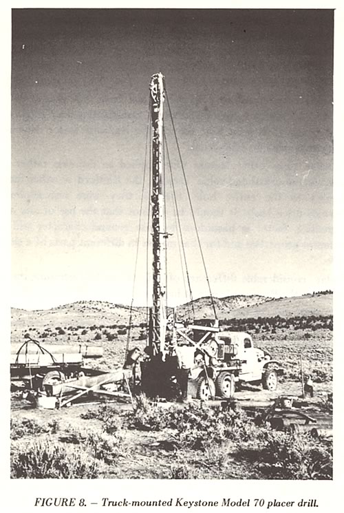
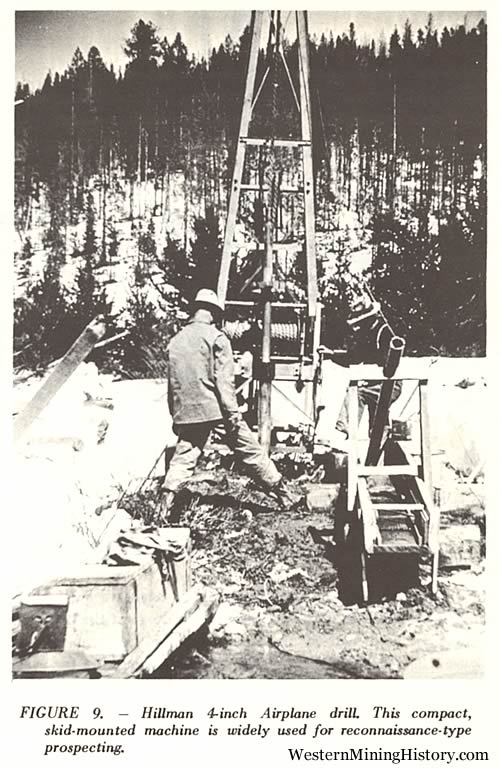
Most placer-type churn drills used in the United States are powered by gasoline engines and designed for use with 6-inch drive pipe and tools. Typical arrangements are illustrated by Figures 8 and 9. Drills in common use are the Keystone Model 70 (Now called "Speedstar"; manufactured by Buffalo-Springfield Co., Enid, Oklahoma (successor to Keystone Driller Co.) ), a truck-mounted unit for use with 6-inch pipe; the Keystone Model 71, a 6-inch traction drill mounted on a crawler base; the BE 22-T (Manufactured by Bucyrus-Erie Co., South Milwaukee, Wisconsin), a crawler-mounted 6-inch drill; the Hillman Prospector (Manufactured by C. Kirk Hillman Company, Seattle, Washington), a 6-inch truck or crawler-mounted rig and the Hillman Airplane Drill. a compact, skid-mounted machine designed for use with 4 or 5-inch drive pipe. A crawler-type traction drill complete with 40 lengths (about 240 ft.) of drive pipe and the necessary tools will weigh 10 to 15 tons.
Hand-powered drills are widely used in foreign fields and regions where access is difficult and labor cheap. The Banka or Empire drill employs a rotating casing equipped with a serrated cutting shoe. The Ward hand-powered drill employs 4 or 5-inch drive pipe and standard tools.
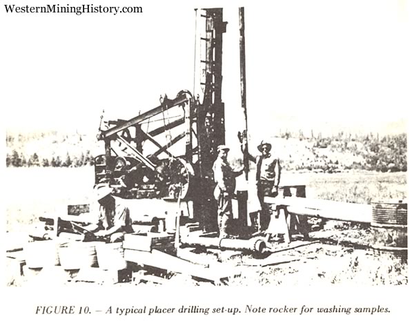
A drill crew usually consists of the driller who is responsible for operation of the drill, a helper to assist with general work and handling the tools and a panner who must process the samples and keep an accurate log of the hole as it progresses. A typical placer drilling set-up is shown in Figure 10. A fourth man may be required where water must be hauled or drill sites prepared. An experienced driller has become so accustomed to the sound of drilling and the feel of the drill line, he can usually tell just what is happening in the hole. By keeping careful watch and logging all pertinent data, he provides the information needed by the engineer for "correcting" the indicated values. The panner who should have some technical as well as practical training, often serves as the crew foreman.